9. System integration#
This chapter provides an overview of the systems that can be integrated into NAVIGATOR, along with their respective settings.
Hint
Specific use cases are presented at the end of the chapter.
9.1. SensorHandler setup#
9.1.1. Supported sensors#
IMU
iXBlue AIRINS / ATLANS
Cameras
Vexel UltraCam
Sybsec
HySpex
Nikon
Canon
IGN Camera
InfraTec VarioCam HiRes 640
CWIS-II DCS
Simplex
LiDAR
Sensor mount platforms
GSM3000
AeroStab3
PAV80
SteadyTrack
General purpose sensor handling
9.1.2. Setting up integrated sensors#
This chapter is primarily intended for system integrators.
9.1.2.1. Setting up the SensorHandler sensor list#
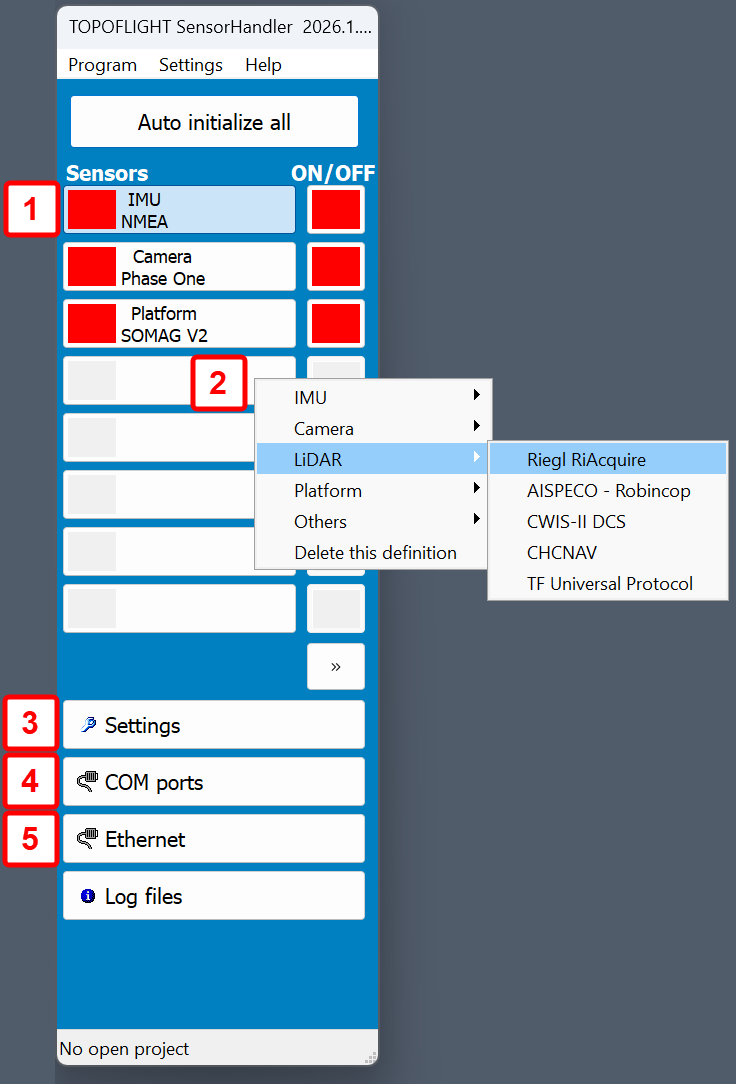
Each button on the left of the SensorHandler panel represents a device being used. Right-click on a button to add or remove a device from the list of devices.
|
1 Populated button: in this example SensorHandler will use NMEA to communicate with the IMU. 2 Empty button: right-click on it and select a sensor from the list to populate that button 3 In the settings the following information is stored:
4 Click the COM ports button, select a sensor and define the COM port requried for your configuration. 5 Click the Ethernet button, select a sensor from the drop-down menu and define the ports requried for your sensor configuration. |
9.1.2.2. Examples of COM port and Ethernet definitions#
9.2. Setting up IMUs#
9.2.1. Setting up Applanix POS AV#
9.2.1.1. SensorHandler settings for POS AV#
9.2.1.2. Applanix POSView program settings#
The Applanix program POSView controls the IMU settings. Make sure the following settings are made in POSView Ethernet Real-Time Port 2:
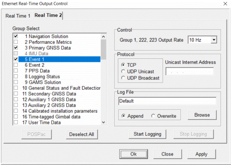
Enable the following groups:
1: Navigation solution
3: Primary GNSS Data
5: Event 1
200: Gimbal Encoder Data
203: Gimbal Yaw Drift Correction Data
-
222: Reference frame Navigation solution, only if you use direct control of the mount with the special handler for somag mount V2 (by default group 222 is not activated).

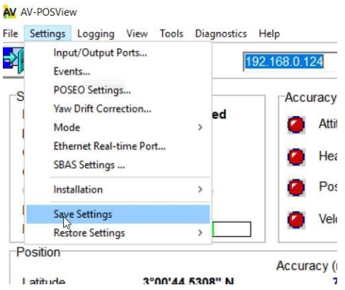
Store the settings in PosView:
9.2.2. Setting up Applanix AP+#
SensorHandler needs two ports to communicate with Applanix AP+:
TCP/IP to get navigation data (it is usually defined as port
28001)TCP/IP to get event information (it is usually defined as port
28002)
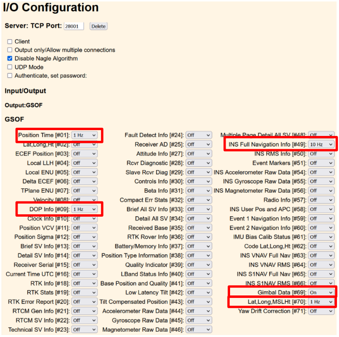
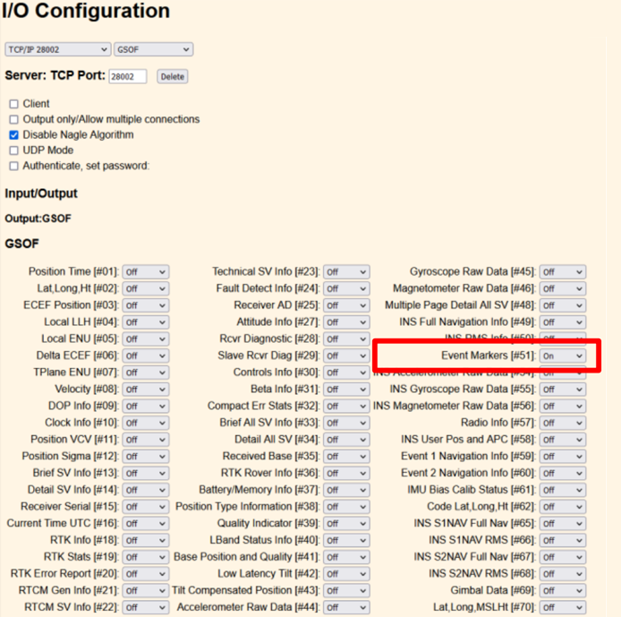
9.2.2.1. Definition in web interface of Applanix AP+#
Ports 28001 and 28002 are used. These are the default ports but other port numbers can also be
used.
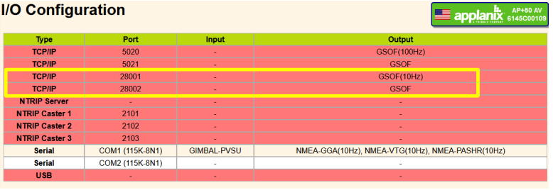
Definitions for navigation data (port 28001):
Definitions for event (port 28002):
9.2.2.2. Settings in SensorHandler#
Important

Instead, enable it in the RiACQUIRE dialog:

9.2.2.3. Remarks for controlling a gyro mount#
Important
The mount will only switch to STAB mode (unfreeze) when the aircraft is inside the corridor.
The green box signifies that the mount is in MAN mode (freeze). The aircraft is outside the corridor, so the two buttons (set manually ON, set manually OFF) can be activated.
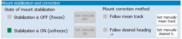
The green box signifies that the mount is in STAB mode (unfreeze). The aircraft is inside the corridor. Therefore, the two buttons (Set manually ON, set manually OFF) cannot be activated.

|
A prompt indication of whether the mount is in stabilization mode is provided through the icon displayed in the main window of the NAVIGATOR program, see Status of MNT - SOMAG Mount. |
9.2.3. Setting up NMEA#
Any device capable of sending NMEA sentences is compatible with NAVIGATOR. For navigation, only the following sentences are needed:
GPGGA
GPVTG or GPRMC
9.2.3.1. Setting up NMEA in SensorHandler#
Hint
Remember to define the port (COM or TCP) through which the device can be reached.
9.2.3.2. Settings for NMEA in SensorHandler for TCP/IP or UDP#
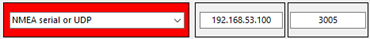
9.2.4. Setting up Novatel using NMEA#
The integration into SensorHandler follows the same approach as outlined here for NMEA.
The Novatel Ethernet and port settings may appear as shown in this example (192.168.53.100 and 3005):
9.3. Setting up cameras#
9.3.1. Setting up ITRES#
9.3.2. Setting up a Phase One camera#
By default, Phase One and iXCapture both run on the same computer (usually on an iXController). The operator thus can see the images taken (with iXCapture) while also seeing the navigation window of the flight. This default installation implicates that SensorHandler runs on the same machine.
Some special installations are required to run iXCapture on a different machine than that of the navigation program. In this case, NAVIGATOR and SensorHandler run on one machine and iXCapture on another.
9.3.3. Setting up a universal camera#
By using an external trigger cable it is possible to control any kind of camera.
Requirements:
external trigger cable (camera specific)
optional: hot shoe adapter (incl. cable)
the cables are connected to the flight computer via COM port
9.4. Setting up LiDAR sensors#
9.4.1. Setting up Riegl RiACQUIRE#
9.4.2. Standard and alternative image capture methods#
The sketch below illustrates two methods for triggering the camera to capture an image.
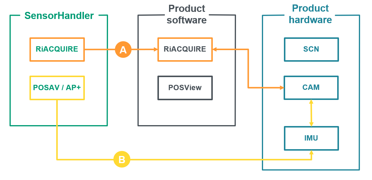
In the standard method (A), the image capture settings are configured in the SensorHandler RiACQUIRE menu. These settings are then transferred to RiACQUIRE, which communicates directly with the camera to trigger the image.
In the alternative method (B), the settings are configured in the SensorHandler POS AV menu. These settings are passed directly to the IMU, which in turn triggers the camera.
9.5. Setting up sensor mount platforms#
9.5.1. Using the SOMAG mount handler#
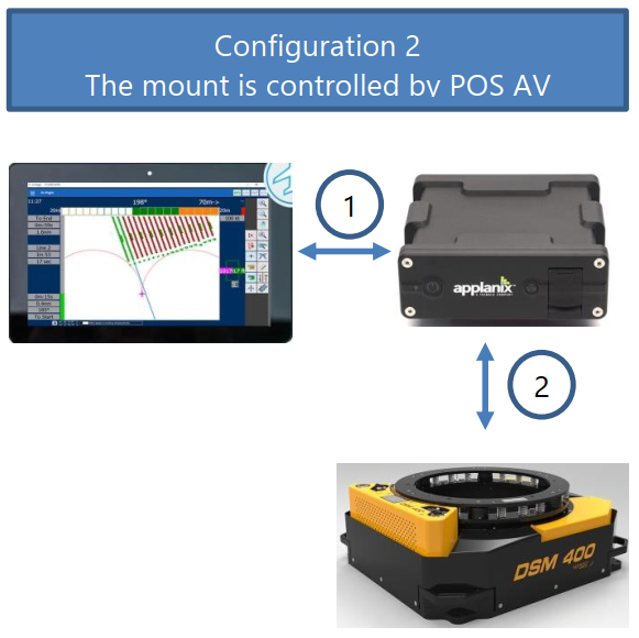
9.5.1.1. The two main configurations#
Important

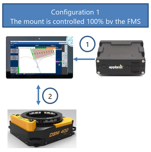
(A) The mount is controlled by the FMS |
(B) The mount is controlled by the IMU |
|
|
|
|
1 The IMU sends position data to the FMS. This is usually done by Ethernet but it can also be done by serial communication. |
1 The IMU sends position data to the FMS. The FMS sends freeze / unfreeze to the IMU. |
|
|
2 The FMS is connected to the mount. The FMS does the whole control of the mount:
|
2 The mount is connected to the IMU. The IMU fully controls the mount:
|
|
No mount angles are logged. |
The mount angles can be logged on the IMU. |
9.5.1.2. Basic modes of operation#
This handler is used to control all the gyro mounts of the SOMAG AG Jena, running Protocol Version 2.0 .
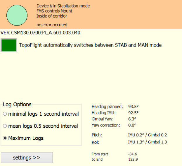
In standard mode, the mount will be set to STAB mode before the flight line starts and will be set to MAN mode after the line has been finished or when the line is left. The following angles need to be known to drive the mount accurately to the needed position:
pitch, roll, heading angles coming from the IMU
ground track heading coming from the GNSS
actual yaw angle of the mount
the desired heading angle the mount should to be driven to. This heading angle can either be the heading of the planned flight line or of the ground track.
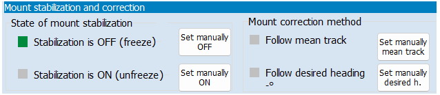
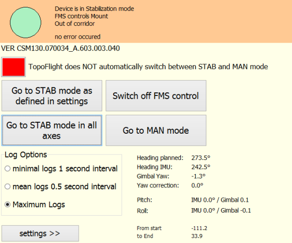
For special cases (like testing the mount), the automatic control of the mount can be switched off:
After switching off the automatic mode, the mount won’t switch between MAN and STAB mode automatically. This mode is mostly used for testing system components like communication and behavior of the mount.
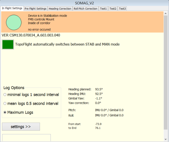
9.5.1.3. Pre-flight settings#

1 |
Checked by default to enable heading corrections. This means that the IMU yaw angle will be corrected in accordance with the received IMU angles. SensorHandler requires the actual yaw of the gimbal in order to calculate the amount of correction for accurate yaw positioning of the mount. Here, you set the time intervals in which actual gimbal angles are sent to SensorHandler. Normally, a value of 100 milliseconds is used. Select the method for heading correction:
The following sketch illustrates the distinction between the modes Set Drift to Ground Track (on the left) and Set Drift to Planned Heading (right): 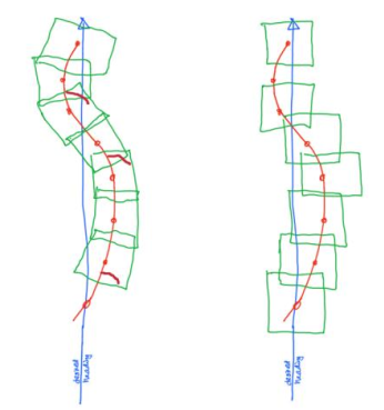
|
2 |
Checked by default for transmission. This means that roll and pitch angles coming from the IMU are used to increase the accuracy of the mount’s stabilization process during flight. |
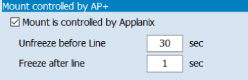
3 |
In the edit fields, you define how many seconds before the start of the flight line the mount will go into STAB mode and how many seconds after the end of the flight line the mount will switch back to MAN mode. |
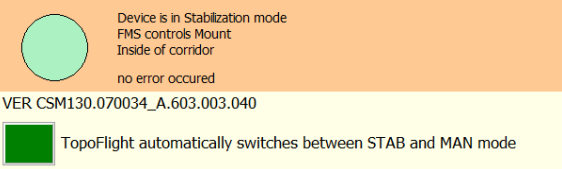
9.5.1.4. Automatic transition between STAB and MAN mode#
|
While on the flight line the mount is automatically set to STAB mode |
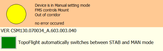
|
After having left the flight line the mount is automatically switched back to MAN mode |
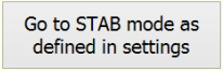
9.5.1.5. Manual transition between STAB and MAN mode#
|
switches back to automatic mode |
|
sets the STAB mode for all axes (roll, pitch, yaw) |
|
STAB mode is switched off and MAN mode is activated |
|
|
9.5.1.6. For system integrators: COM port settings#
The SOMAG mount and SensorHandler communicate through serial communication, requiring accurate configuration of the corresponding COM port settings.
Tip for system Integrators
Important
Read the section below on how to verify the proper functionality of SensorHandler in conjunction with the SOMAG mount!
Often, when integrating a system, you have the mount on the table but do not yet have an IMU available. Switch the mount without a connected IMU to STAB mode. You will notice that the mount moves slightly to the end stops (it does not really stabilize). But you can check if SensorHandler and mount behave correctly.
You can perform this system check by forcing SensorHandler to send the mount gimbal angles back to the mount as simulated IMU values. Then the mount will be stabilized on the table. Do the following:
9.6. Setting up TOPOFLIGHT universal protocol#
Hint
Go to the chapter TOPOFLIGHT universal protocol for a detailed description of the socket usage, the TCP message structure, the states and state switches as well as the usage of the TOPOFLIGHT universal protocol.
9.7. Use cases#
9.7.1. Riegl / Phase One / POS AV#
Toolset
Sensor: Riegl scanner with built-in Phase One camera
IMU: Applanix POS AV
Settings
9.7.2. Riegl / Phase One / AP+#
Toolset
Sensor: Riegl scanner with built-in Phase One camera
IMU: Applanix AP+
Settings
9.7.3. Helicopter flights#
When using NAVIGATOR in a helicopter, we recommend to apply helicopter specific settings to enhance navigation and reduce pilot workload.
9.7.4. LiDAR without images#
There are two common scenarios for using LiDAR without images:
During flights planned for both LiDAR and camera use, all cameras can be disabled to operate only the scanner (for instance, when transitioning from a daytime to a nighttime flight).
A flight plan may be specifically designed for LiDAR operation without capturing images.
We recommend the following settings: