9. Settings#
To configure various general settings, navigate to ![]() Settings in the Navigation bar.
Settings in the Navigation bar.
Hint
Display and flight line settings for TOPOFLIGHT MISSIONPLANNER can be modified in the individual secondary sidebar menus and in the layers panel.
9.1. General settings#
Go to the Navigation bar Settings menu and open the dialog box to configure general display, flight line and elevation data settings.
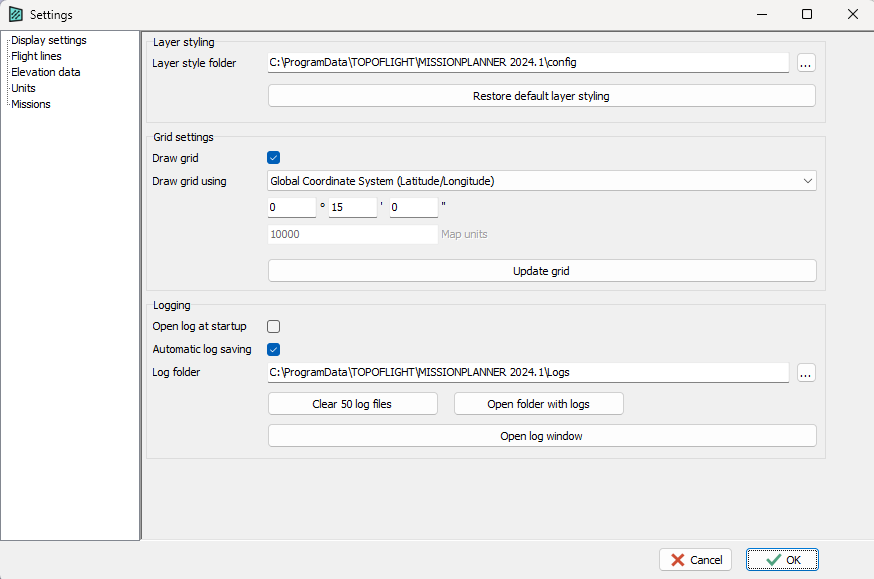
9.1.1. Display settings#
In the Navigation bar Settings menu, choose Display settings.
Layer styling
In the section Layer styling, select the path to the directory housing your personalized layer styling. Find out more about customized layer styles in the layers panel settings.
It is also possible to revert to the MISSIONPLANNER default styling by clicking Restore default layer styling.
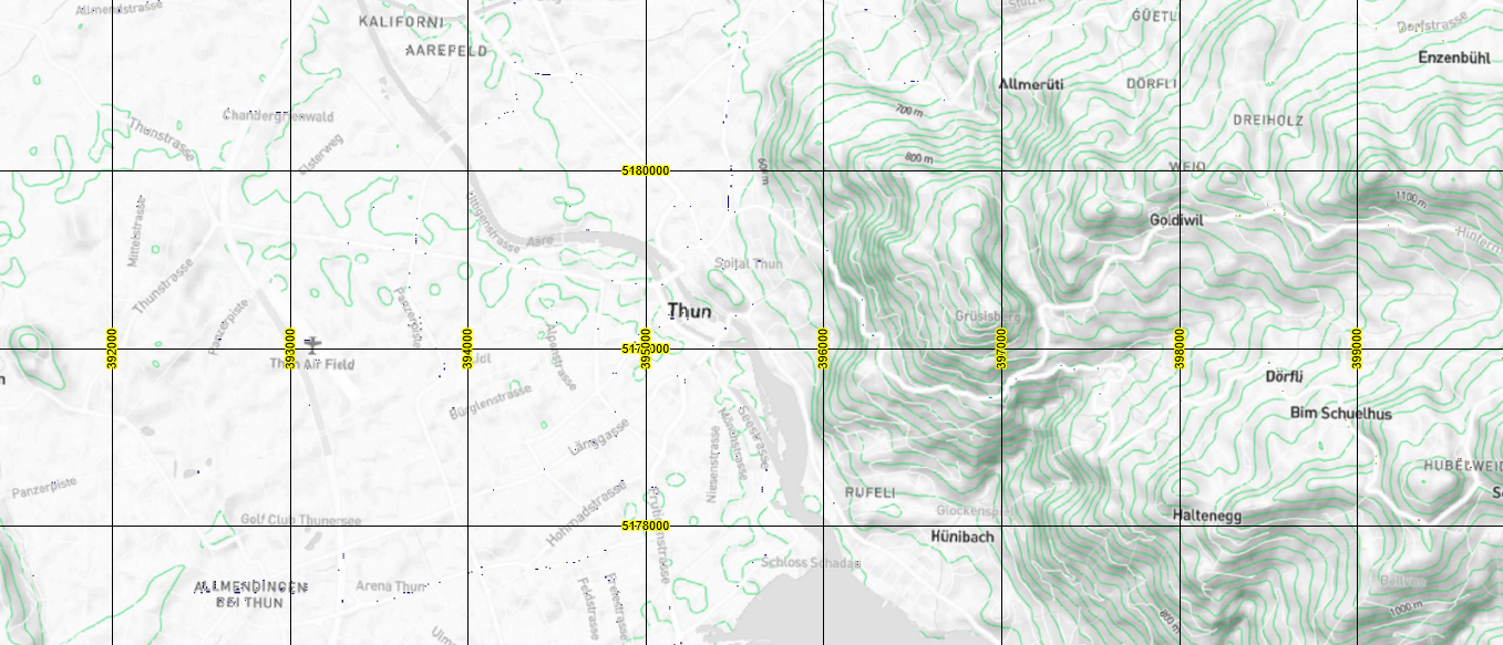
Grid settings
Important
Remember to click on Update grid after checking or unchecking the Draw grid box or making changes to the grid settings before proceeding to the Okay button.
Hint
Define the scale of the map by clicking on the scale positioned at the bottom-right corner of the workspace.

A dialog box opens in which the scale of the map can be defined, e.g. 1:50’000.
Logging
Various options for logging files are available at the bottom of the settings window (rubric Display settings), including opening the log at startup, automatic log saving and changing the log folder location. Click Clear log files to delete log files or Open folder with logs for quick and easy access to existing log files.
Hint
Some log messages can be used for flight line and point editing, see log options.
9.1.2. Flight lines#
In the Navigation bar Settings menu, choose Flight lines.
Flight line settings
Set the main flight line properties:
-
Minimum flight line length [m]All flight lines will be at least this long.Use this setting to make sure all calculated flight lines are long enough for reasonable flight maneuvering.
-
Minimum gap length [m]The gap between two flight lines will be at least this wide.
-
Minimum HAGL [m]All calculated flight lines will be at least this high above the ground level.This function ensures that the averaged flight line heights will be at least the specified height of meters above e.g. any mountain peaks.
Important
Caution: this HAGL setting will overwrite the HAGL set in the sensor configuration.
-
Number of image points per sideThis number determines how many points are calculated between the corner points of footprints.Recommended setting: 1Increasing this number will increase the computation time.
-
Extend flight line to the last image centerCheck or uncheck this box according to your requirements.When selected, the required image overlap is maintained even for the last point of the flight line.
-
Line numberingSelect whether to increase the Parent ID or Segment ID
-
Image numberingSelect whether the image identifiers should commence at 0, 1, or if unique values are preferred throughout the entire project.
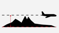
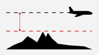
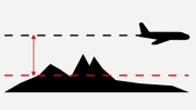
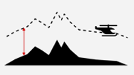
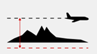
Flying height calculation
Flying height lines can be calculated using one of four distinct methods. The selected approach is displayed in the figure to the right of the parameters.
|
Min. terrain Lowest terrain elevation |
|
|
Max. terrain Highest terrain elevation |
|
|
Mean terrain elevation Recommended in most scenarios |
|
|
Terrain following mode Constant height above ground |
|
|
Fixed altitude Enter value in [m] or [ft]. |
|
Check Allow line stepping to enable steps in height in an individual flight line. This can be useful when there are large differences in height along a flight line and the mean terrain elevation becomes unsuitable.
Important
Line stepping must be used with caution since it interferes with the min. HAGL!
Terrain following mode for CSV import
When image positions are imported via CSV, MISSIONPLANNER automatically generates flight lines. MISSIONPLANNER requires clarification whether the positions are at the same flying altitude or were planned in terrain following mode. For this reason, there is this setting to manage the threshold.
Important
Upon CSV import, users should specify the threshold (% of HAGL) MISSIONPLANNER uses to identify terrain variations.
Overlap calculation
The maximum intermediate angle between flight lines for which overlaps will be calculated can be defined in order to include or exclude adjacent flight lines.
9.1.3. Elevation data#
In the Navigation bar Settings menu, choose Elevation data.
SRTM download
Set the following elevation data properties:
-
SRTM Download PathSpecifies the folder where downloaded SRTM files for your projects are stored.You can change the default folder to another location.
Important
Always use a folder you can reliably access - do not use server locations.
-
SRTM no data valueSpecifies the value in meters to use when SRTM data is not available, for example, above an ocean.Default value: 0
Copernicus download
Set the following elevation data properties:
-
Copernicus Download PathSpecifies the folder where downloaded Copernicus files for your projects are stored.You can change the default folder to another location.
Important
Always use a folder you can reliably access - do not use server locations.
Terrain coloring
Set the color scheme for differentiating between different altitudes in the SRTM data.
Important
The new terrain color map you choose will only come into effect once you have redownloaded your elevation model.
Enable the use different color option to visually distinguish terrain elevations at or below sea level. Then, select a custom color to represent these areas.
Vertical datum
Use EGM96 geoid: height reference system of the SRTM tiles and most other elevation data
Use EGM2008 geoid: used for Copernicus elevation data
-
Reduce to WGS84 ellipsoid (default): activate to reduce SRTM data from EGM96 Geoid to WGS84 ellipsoid
Important
Your flight plan altitude values will be based on the WGS84 ellipsoid. Verify that your GPS/IMU settings are configured accordingly!
Geoid models
To convert between elevation models, geoid models are needed. These models are available on our website. Use the respective button to download and save the EGM96 or EGM2008 model in the specified folder.
9.1.4. Missions#
Go to the Navigation bar Settings menu and open the dialog box to configure various mission-specific settings.
Configuring the operators
Rename the current operator and update the list of available operators.
Click
 and insert the name of a new operator in the dialog window.
Click an available operator’s name to highlight it, then click the
 icon to delete that operator from the list.
Default aircraft settings
Adjust the default mapping speed, transfer speed and turn time of the aircraft for accurate mission-related calculations, such as the flight time.
Flight line and image point appearance
Set the basic color of each flight line status by clicking on the respective color box.
Set the line color and width of lines that are in/not in a mission.
Set the point size, border color, point color and flight line width for the display of mission-related flight lines and images.
Set the label and shadow color, font size and display options of flight line and image labels.
Set the 1D and 2D color as well as the line width for the representation of deviation vectors.
Hint
Further mission-specific flight line and image display settings can be found in the Mission management secondary sidebar menu.
9.2. Customizing layers#
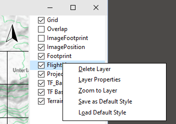
Various layer options, such as the name of the layer or its transparency, can be accessed by double-clicking on a layer in the layers panel or right-clicking on a layer and selecting Layer properties.
Hint
To change the stacking order of the layers between front and back, drag each layer up or down as required.
9.2.1. Customizing layer properties#
Users can define and save the properties of symbols, lines and other elements utilized in the individual layers.
9.2.2. Saving layer styles#
9.2.3. Loading layer styles#
9.2.4. Deleting layers#
Prior to deleting a layer, a dialog box prompts the user to decide whether to remove the layer solely from the layers panel or delete the entire file from the project folder. Additionally, there is an option to cancel the action altogether.
9.2.5. Zooming to layers#
9.3. 3D view mode#
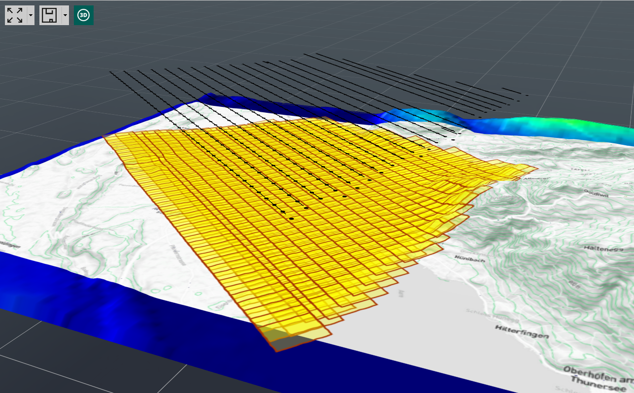
Get a more comprehensive perspective of your flight plan through 3D visualization. Click on ![]() in the top left corner of the workspace. Utilize the left mouse button by clicking and holding to manipulate and rotate the perspective. The 3D view is only applied to layers it has been activated for.
in the top left corner of the workspace. Utilize the left mouse button by clicking and holding to manipulate and rotate the perspective. The 3D view is only applied to layers it has been activated for.
Important
Prior to switching to the 3D mode, configure the current 2D view to display the content you wish to observe in the 3D environment, e.g. by clicking ![]() for choosing the entire project extent. Subsequently, click
for choosing the entire project extent. Subsequently, click ![]() to ensure that the visualization encompasses more than just a zoomed-in area.
to ensure that the visualization encompasses more than just a zoomed-in area.