6. Settings#
6.1. Overview#
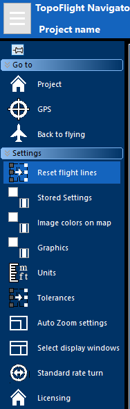
Clicking on the bar symbol on the top left will open the main settings.
|
|
6.2. Missions#
TOPOFLIGHT’s Mission management feature enables the division of projects into individual missions. In releases from 2026 onward, users can open a selected mission instead of the complete flight plan to view only mission-specific lines. It is also possible to import and export .TFX files as well as to create reports for individual missions.
6.3. Selecting the GPS#
In the main settings menu, select GPS.
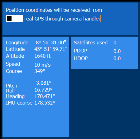
The option GPS through SensorHandler uses the coordinates delivered by SensorHandler from the external GPS.
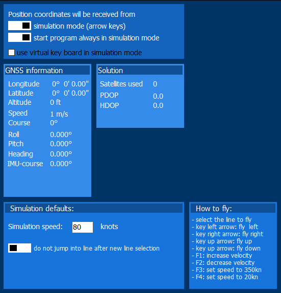
Simulation mode uses computed coordinates from the flight simulation instead of real GPS data (see simulation mode for more details).
6.4. Back to flying#
In the main settings menu, select Back to flying to leave the settings and go back to the flight navigation.

6.5. Reset flight lines#
6.5.1. Overview#
The color of the flight lines and dots shown on the map indicates the status of the lines and images. These colors can be personalized in the map graphics settings.
Default line or dot color |
Flight line or image status |
|---|---|
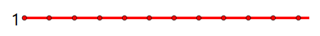
|
successful |
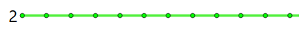
|
warning |
|
error |
|
marked for refly |
|
not flown |
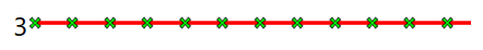
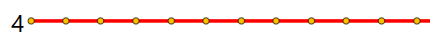
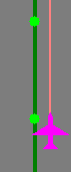
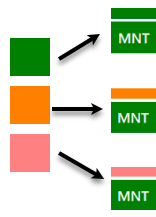
As images and LiDAR lines are acquired independently by separate sensors, the resulting dot and line color combinations depend on the collected data. The following example shows successfully captured images with an error in the LiDAR data acquisition: 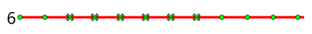
It is possible to reset the status of an entire flight line, a section of a line or that of of individual images.
Hint
These adjustments can easily be made during a flight, see below.
6.5.2. Reset flight lines#
6.5.3. Reset images#
6.5.4. Examples#
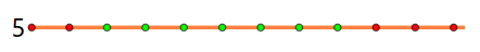
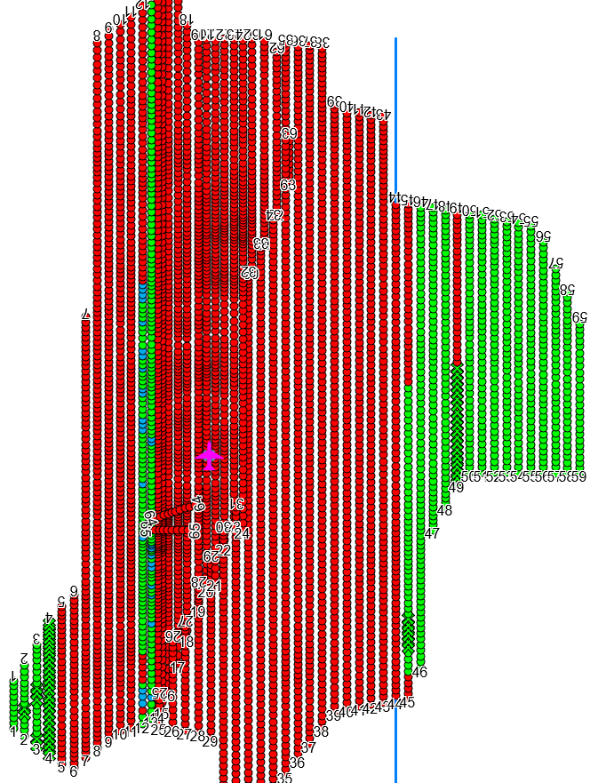
Example of a flight plan with different flight line statuses
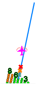
The graphic below shows a plan with fully flown, partially flown and not flown lines with the default coloring scheme: successful, warning, error, marked for refly, not flown.
Example of how to manually change the image status
Status changes can be made manually for individual (or all) images of a line.
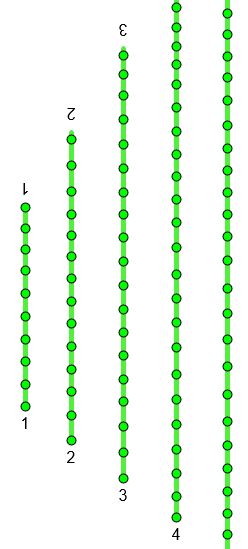
The green color indicates that all images on the lines 9 to 12 were captured successfully. After a closer inspection it was found that the landscape was covered in snow on the first 6 images of line 10. These images will have to be retaken at a later date and, therefore, are to be marked.
Result:

Images 1 to 6 of line 10 are now colored yellow.
6.6. Capture mode#
In the main settings menu, select Capture mode. From the 2026 release onward, three capture modes are available:
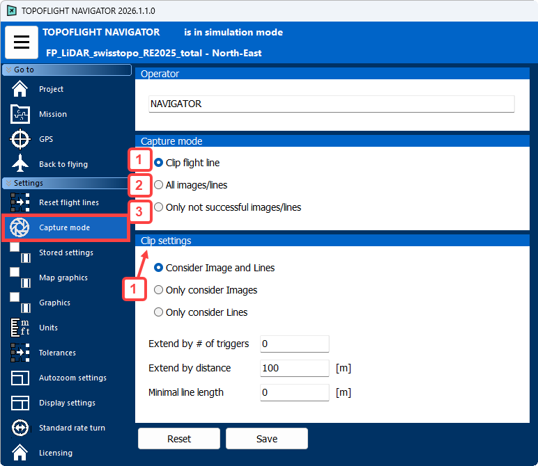
1 |
Clip flight line to the remaining images and line sections. This enables an easier approach when the line is reflown.
|
2 |
Trigger all images and/or lines |
3 |
Trigger only the images and/or lines sections that have not yet been triggered successfully |
Hint
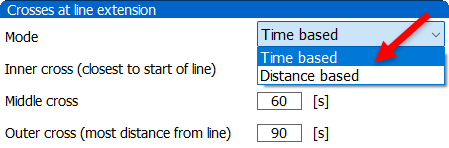
In edge cases, NAVIGATOR uses whichever extension is larger - either the one based on the number of triggers or the one based on the specified distance.
6.7. Stored settings#
The default folder for the settings is ../ProgramData/TOPOFLIGHT/NAVIGATOR [version]/Settings/. Any adjustments made to the original settings will be stored here.
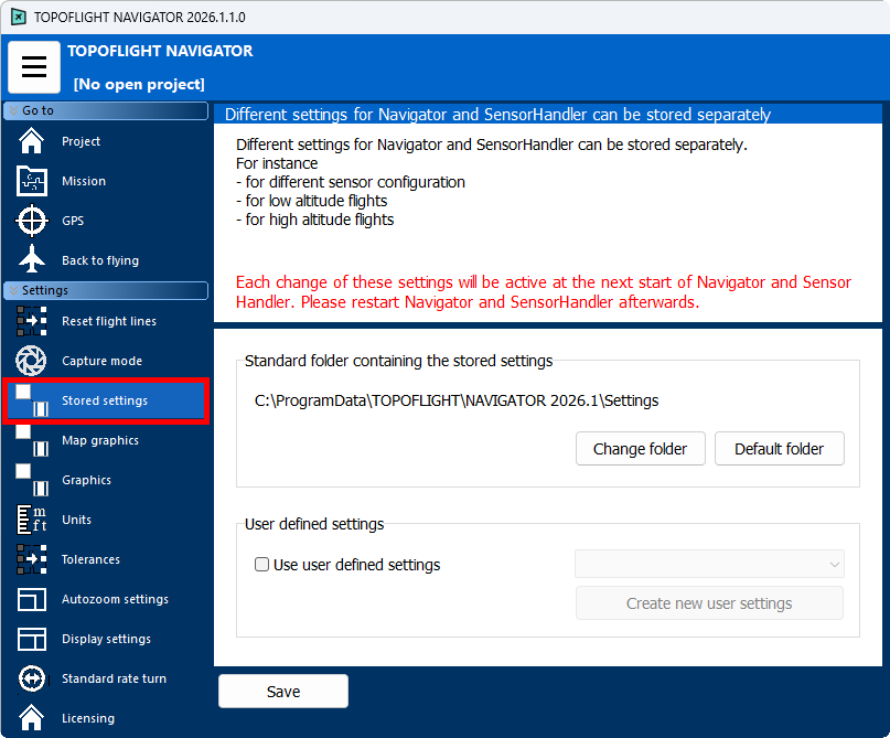
You can create individual profiles for different requirements and save those settings separately. For example, you might want separate profiles for flight duration, low- or high-altitude operations, the systems in use, or pilot preferences. These individual NAVIGATOR and SensorHandler settings are stored as distinct ini-files in a new folder within the default settings directory.
Hint
The possibility to save different settings has an advantage for companies operating different sensor systems. A separate set of ini-files can be saved for each configuration. E.g., if a company has a one system with a Riegl scanner and Phase One cameras, a second system with an UltraCam camera and a third system with an ITRES multispectral scanner, then separate settings can be saved and reloaded for each of these three systems.
Important
Previously, a new installation of NAVIGATOR overwrote the existing ini-files in the folder ../ProgramData/TOPOFLIGHT/NAVIGATOR [version]/Settings/ with the default values. Users were required to make a backup of the ini-file folder before a new installation and later copy it back into the corresponding folder. As of version 15, the settings are saved separately and are maintained for new installations.
Important
When NAVIGATOR starts, it automatically applies the most recently used settings.
6.8. Map graphics#
In the main settings menu, select Map graphics. Click on the individual colors to define a personalized color scheme for the map, the airplane and the image centers. It is also possible to adjust the size of the airplane symbol and that of the image dots. The default scheme uses the color definition and size shown in this manual.
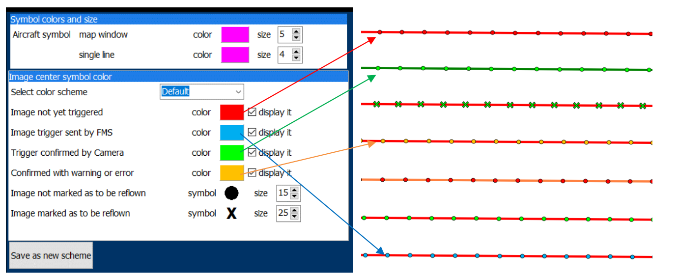
Hint
All values associated with the aircraft (speed, altitude, azimuth and map icon) in the operator and pilot windows share the color assigned to the airplane symbol.
6.9. Graphics#
6.9.1. Customizing font and UI colors#
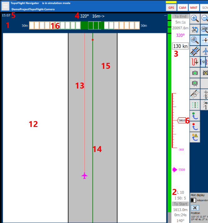
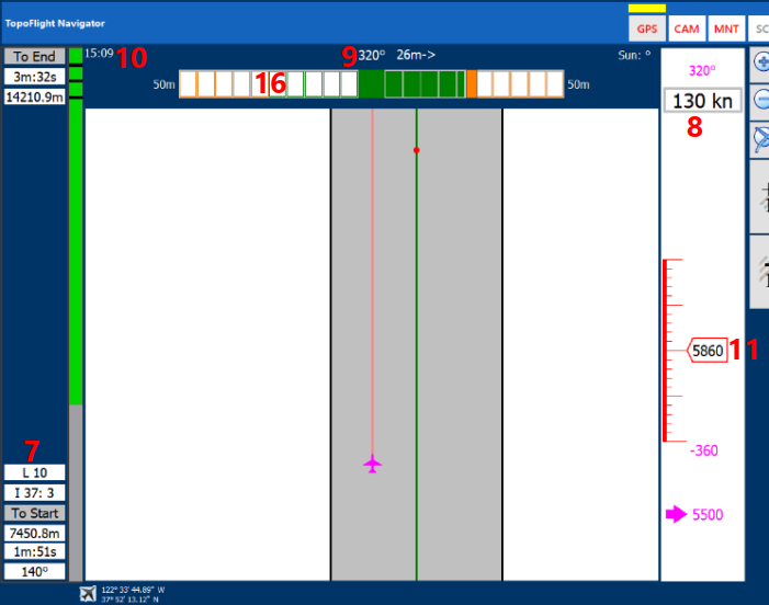
In the main settings menu, select Graphics. Set e.g. the UI color, symbol sizes and fonts for various user interface elements according to your preferences.
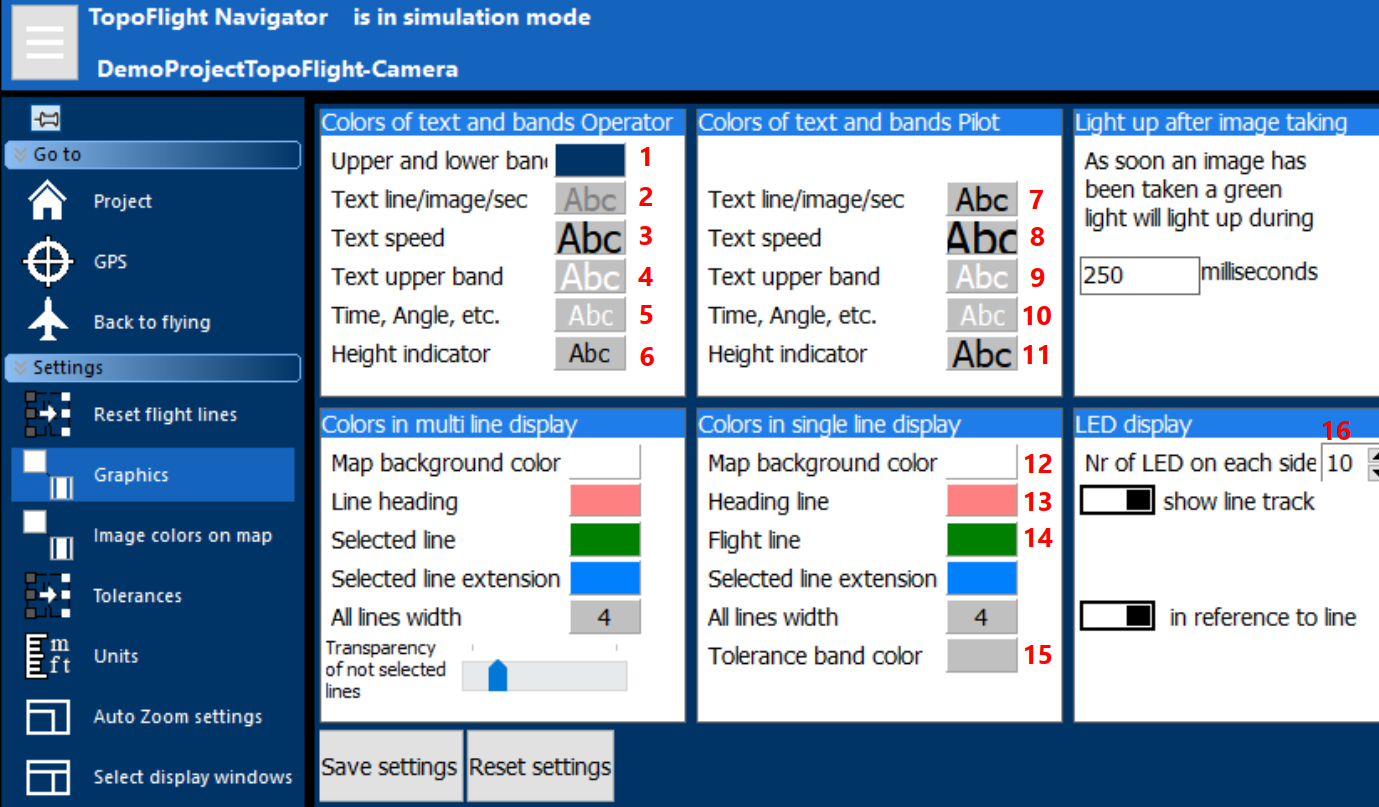
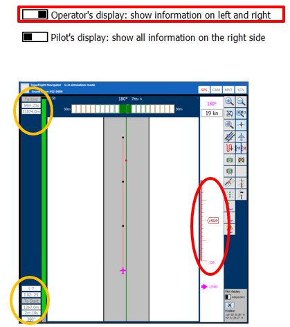
Red numbers in the graphic above mark different options. In the illustrations below, these numbers show the corresponding user interface elements that are affected by these settings.
Operator’s display: |
Pilot’s display: |
|
|
6.10. Units#
In the main settings menu, select Units. The currently selected units are highlighted in light blue.

|
|
6.11. Tolerances#
In the main settings menu, select Tolerances.
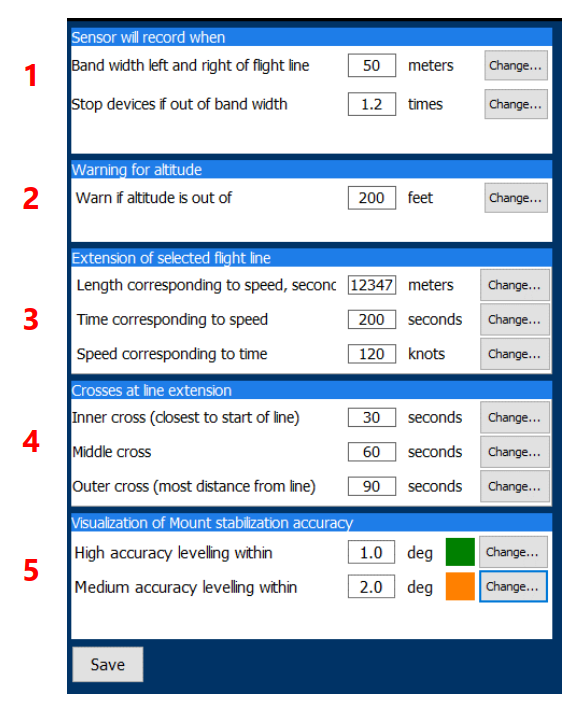
1 |
Horizontal distance from line: Images will be taken when the sensor is within the tolerated horizontal distance. This value has an effect on the
|
||||
2 |
Flying altitude tolerance:
|
||||
3 |
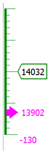
Line extension markers:
|
||||
4 |
Visualization of mount accuracy:
|
||||
5 |
Speed tolerance exceedance: Select the intended or defined speed, then specify the threshold for warnings when the actual speed is faster/slower than it and click Apply. The new settings will be applied after the next flight line has been selected. |

6.12. Autozoom settings#
In the main settings menu, select Autozoom settings.

1 |
Select Head-up or North-up mode for the orientation of the map. By default, the view will automatically switch to head-up mode when inside the flight corridor and will revert again once outside the corridor. This setting can be changed, see below (2). |
||
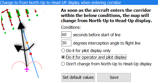
2 |
Enter the conditions upon which the operator and the pilot display change to head-up mode when entering the corridor or select to always keep the north-up mode selected above (1). In this example, the display will change as soon as the airplane is less than 60 seconds from the start of the line and/or has reached an interception angle of less than 30 degrees between the track angle of the airplane and the selected line. |
||
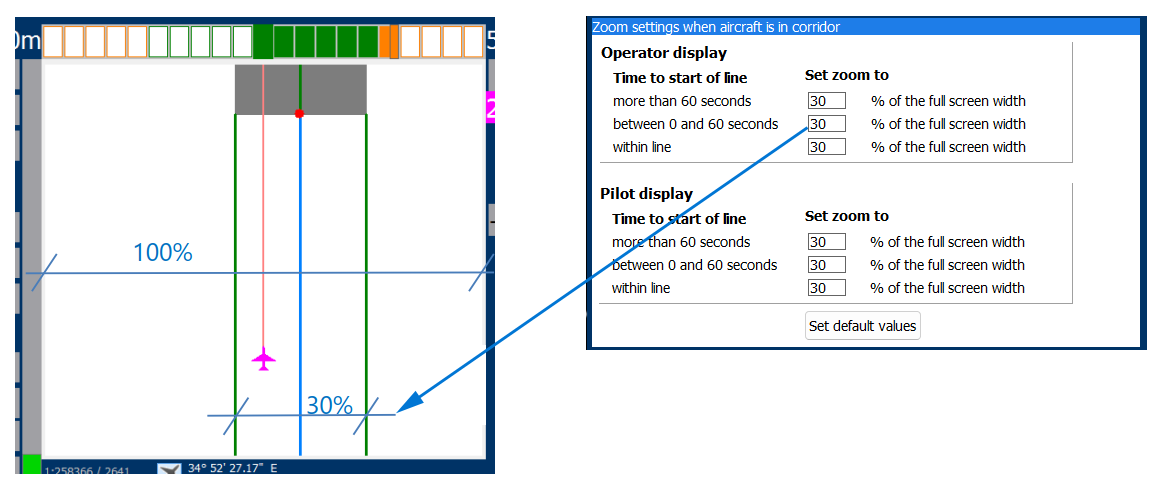
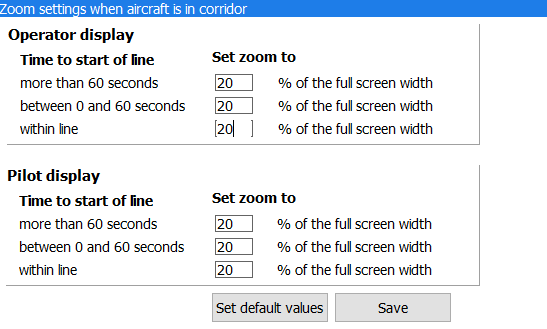
3 |
Specify the zoom level for when the aircraft is within the corridor. In this state, the display always switches from multiline to single-line view. Individual zoom percentages can be defined for different time intervals and for both the operator and pilot displays.
|
6.13. Display settings#
Important
To support this setup, the Windows operating system must be set to extend the desktop.
In the main settings menu, select Display settings to set up the operator and pilot display.
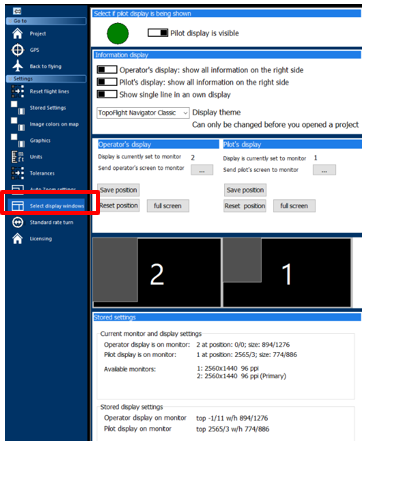
1 |
The pilot display (Pi) runs independently from the operator display (Op). |
||
2 |
Toggle the switch at the top to hide the pilot display. |
||
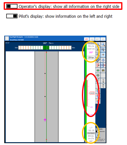
3 |
Select Right side to display the time and distance bar and the altitude on the right side only. Select Left side to display the time and distance bar on the left (the altitude remains on the right). On larger displays (typically the operator display), the information is usually shown on the right side only.
|
||
4 |
Click on the ellipses and then select a monitor from the dropdown menu to move the pilot or operator display from one screen to the other without a mouse. This is particularly convenient when you have a touch screen and manual positioning of the window is not suitable. |
||
5 |
Full screen: clicking this button enlarges the operator or pilot display to cover the whole screen. |
||
6 |
Save the actual position and size of the operator or pilot display. The next time the program is started the position of the operator/pilot display is positioned in the saved location. |
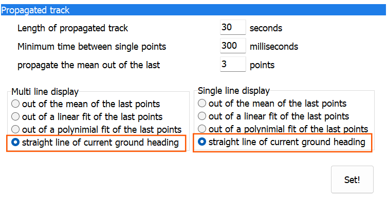
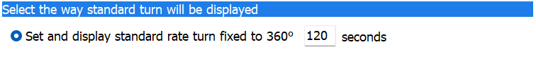
6.14. Standard rate turn#
In the main settings menu, select Standard rate turn.

1 |
|
||
2 |
Adjust the visualization of the propagated track. Individual settings for multi line and single line displays are possible. |
6.15. Helicopter specific settings#
The default installation of NAVIGATOR includes some predefined settings that are optimized for use in an airplane. If NAVIGATOR is being used in a helicopter, certain adjustments may be necessary to enhance navigation and reduce pilot workload.
Here are some suggested settings for helicopter flights:
Auto zoom settings - Interception angle
The interception angle is set to 10 or 20 degrees by default. In a helicopter, set the interception angle in the auto zoom settings to 20 degrees. This helps minimize the frequent switching between single line and overall display modes.
Auto zoom settings - Aircraft in corridor
The default zoom level is set to 30%. However, you may find 20% to be more convenient in order to have a broader view when the helicopter is within the corridor. It is recommended to test this setting during flight and adjust the level in the auto zoom settings according to your preference.
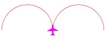
Standard rate turn - Display
The standard rate turn is shown as “moustache” in the operator and pilot display. For an aircraft it is set to 120 seconds for a full 360° turn. Adjust the standard rate turn to a more convenient value for helicopter turns.
Standard rate turn - Propagated track
The propagated track is typically displayed as a curved line, calculated based on the last three points within the previous 300 milliseconds. However, in a helicopter, this often results in a jittery line due to the frequent changes in ground track. To improve readability, it recommended replace the curved line with a straight one in the standard rate turn settings.