5. Defining flight lines#
This section describes how to use the basic features required for creating a simple flight plan.
Hint
To set general flight line settings, go to the Navigation bar Settings option and click Flight lines.
5.1. Selecting the sensor#
MISSIONPLANNER uses the sensor parameters to calculate flight lines and trigger points.
Important
If you added multiple sensors to the project, select one from the secondary sidebar. The Basic metrics are updated accordingly.
5.2. Configuring flight line basic metrics#
Important
Any parameters that you modify under Basic metrics are also modified in the Sensor settings.
In the secondary sidebar, under Basic metrics, configure the following parameters:
Parameter |
Description |
|---|---|
GSD |
Ground Sample Distance - the distance on the ground that each pixel in an image represents (the physical size of one pixel in the real world). This option does not appear for LiDAR systems. Modifying the GSD adjusts the HAGL accordingly. |
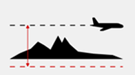
HAGL |
Height Above Ground Level - the difference between the flight altitude and the terrain height. Modifying the HAGL adjusts the GSD accordingly. |
Forward [min] |
The minimal forward overlap between one image and the next along the flight line. Use this value to ensure the image sequence time is met, i.e. the camera has enough time (depending on the distance/flying speed) to capture each image in regard to its hardware capabilities. Hint
|
Sidelap [mean/min] |
The mean overlap between two flight lines. Hint
|
Distance between flight lines |
Use a specified portion of the stereoscopic area to calculate the distance to the next flight line. Modifying the Distance between flight lines adjusts the Sidelap accordingly. |
5.3. Calculating altitude settings#
In the secondary sidebar, under Calculate altitude from, configure the following parameters for the flying altitude and the rounding of the altitude.
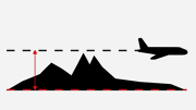
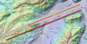
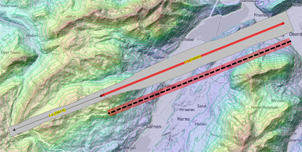
5.3.1. Flying altitude options#
Choose one of five distinct methods for the calculation of flying altitude.
|
Min. terrain Lowest terrain elevation |
|
|
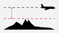
Max. terrain Highest terrain elevation |
|
|
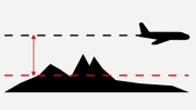
Mean terrain elevation Recommended in most scenarios |
|
|
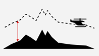
Terrain following mode Constant height above ground |
|
|
Fixed altitude Enter value in [m] or [ft]. |
|
Altitude settings can also be adjusted in the general settings. There, it is possible to enable line stepping. However, that setting must be used with caution as it interferes with the min. HAGL!
5.3.2. Altitude rounding#
At the bottom of the menu Calculate altitude from, select the Rounding checkbox and define the parameters as follows:
Parameter |
Description |
|---|---|
rounding increment |
The step size used to round the altitude. |
unit |
Specifies whether the altitude is measured in feet [ft] or meters [m]. |
up |
Rounds the altitude up to the next multiple of the rounding increment (e.g. 4711 ft → 4800 ft for a rounding increment of 100ft). |
down |
Rounds the altitude down to the previous multiple of the rounding increment (e.g. 4711 ft → 4700 ft for a rounding increment of 100ft). |
closest |
Rounds the altitude up or down to the nearest multiple of the rounding increment (e.g. 4749 ft → 4700 ft and 4750 → 4800 ft for a rounding increment of 100ft). |
5.4. Drawing a flight line#
Important
Flight lines can only be drawn in areas for which elevation data has been downloaded. In the layers panel, make sure the layer containing elevation data encompasses your area of interest. If it doesn’t, navigate to ![]() and update the DTM data.
and update the DTM data.
Important
Copy line: |
Copy segment: |
|
|
5.5. Editing flight lines and segments#
5.6. Deleting flight lines#
5.7. Setting a buffer around an AOI#
It is recommended to add a good buffer around the AOI (minimally as long as the surrounding flight altitude), especially when planning an oblique mission.
Important
While the AOI is selected
it is not possible to draw lines outside the perimeter.
every new flight line inside the AOI is extended to the border of the AOI.
5.7.1. Extending flight lines beyond the AOI#
When adding flight lines, you can specify if and by how much the added flight lines will extend beyond the AOI. The chosen option will apply both to parallel added flight lines as well as flight lines manually drawn by the user. Be sure to select the AOI before adding new lines!
5.8. Adding flight lines automatically#
Important
At least one flight line must be present before you can add additional lines automatically.
5.8.1. Copying a flight line#
Important
You can specify if and by how much the added parallel flight lines will extend beyond the selected AOI.
To copy a flight line to a fixed distance from the original line:
Click
 .
.Choose Type Line or Segment.
Click Copy flight line.
Click Parallel copy (2nd option) and enter the distance in meters that the new line will be from the existing line.
Check the box use altitude from the reference flight line at the bottom of the sidebar to apply the flight altitude (not HAGL!) of the line you want to copy (original) to the new line (copy).
Click the flight line you want to copy (original).
Move the mouse up or down to the target location (fixed distance) and click the map to create the new line (copy).
To copy a flight line in line with the original line:
Click
.Choose Type Line or Segment.
Click Copy flight line.
Click In line copy.
Check the box use altitude from the reference flight line at the bottom of the sidebar to apply the flight altitude (not HAGL!) of the line you want to copy (original) to the new line (copy).
Click the flight line you want to copy (original).
Move the mouse right or left to the target location and click the map to create the new line (copy).
5.8.2. Filling a shape with parallel lines#
Important
You can specify if and by how much the added parallel flight lines will extend beyond the selected AOI.
To fill the selected shape to the left or right of an existing flight line:
-
Select the shape you want to fill.
Hint
At least one flight line must be present in the selected shape.
Click
.Click Parallel lines.
For the spacing, select Optimized (uses sidelap definitions — you can adjust them below or in the Basic Metrics settings at the top; changes in one location automatically update the other) or Equal (define the distance of the fixed spacing below). Equal spacing is recommend for a quick generation of a flight plan over mostly flat terrain.
Click either Fill selected shape left of the line or Fill selected shape right of the line.
Check the box use altitude from the reference flight line at the bottom of the sidebar to apply the flight altitude (not HAGL!) of the line you want to copy (original) to the new lines (copies).
Click the flight line you want to copy (original). The “left” or “right” side of the selected shape is filled with lines that are parallel to the line you selected.
To add a fixed number of flight lines in the selected shape to the left or right of an existing flight line:
-
Select the shape you want to fill.
Hint
At least one flight line must be present in the selected shape.
Click
.Click Parallel lines.
Click Add lines and enter the number of lines you want to add in the Left and/or Right boxes.
Check the box use altitude from the reference flight line at the bottom of the sidebar to apply the flight altitude (not HAGL!) of the line you want to copy (original) to the new lines (copies).
Click the flight line you want to copy (original). The “left” or “right” side of the selected shape is filled with the number of lines you specified up till the AOI perimeter.
5.9. Managing flight line segments#
5.9.1. Breaking a flight line#
Flight lines can be broken when it is necessary to change the image scale due to terrain. After a line is broken, each section is recalculated and assigned its own flight height and segment number.
5.9.2. Merging segments#
Segments from the same flight can be merged into a single line, which is then recalculated, assigned a new flight height and labeled with the lower of the original segment numbers.
5.9.3. Converting segments to lines#
In some cases, it may be helpful to convert a segment into a separate flight line.
5.10. Modifying the altitude of flight line(s)#
5.11. Modifying the direction of flight line(s)#
5.12. Setting the IDs of flight line(s)#
Flight line identification is based on two integer numbers (example: 35-2). The first represents the flight line and the second the segment (or part) of the flight line.
Hint
Search for a flight line ID by using the command CTRL+f. The map in the workspace will zoom in on the line and highlight it with a flashing effect.
5.13. Recalculating flight line(s)#
The recalculation methods use the current Basic metrics displayed in the upper section of the secondary sidebar.
Hint
Create all flight lines using parallel copy and the standard configuration.
In the Basic metrics section of the secondary sidebar, enter a new forward overlap value.
Recalculate image positions for one or more lines as described in the box above.