3. Icon description#
This chapter describes the colored icons displaying sensor status information and the use of the icons for display control of flight lines in the operator and pilot display.
3.1. Sensor status information#
The icons in the upper right corner of the Navigator program show the status of each group of sensors:
3.1.1. Status of GPS - INSS#
|
No GPS available |
|
GPS has an error |

|
IMU alignment is degraded |

|
IMU alignment is aligned for full nav |
3.1.2. Status of CAM -Camera(s)#
3.1.2.1. Different statuses for UltraCam camera#
To display the current and previous status of the camera the two boxes of the CAM icon are used. The smaller, upper box shows the previous status. There might be an error or warning which has not been handled by the user. The larger, lower box shows the current status of the camera.
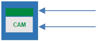
Upper box: Previous status of the camera

|
Operational: the camera is running without errors. No previous unhandled error, warning or information has been detected. |

|
Pending: previously to the active status of the camera, there was an information or warning the user has not yet addressed. |

|
Error previously to the active status of the camera, there was an error on the camera the user has not yet addressed. |
Lower box: Actual status of the camera

|
No camera is available. |

|
The camera is available but not yet connected to SensorHandler. |

|
The camera is not ready to take images. Change camera to ready mode to take images. |
|
|
Green font on gray background: the camera is ready to take images. The airplane is outside the flight line. Manual image triggers are possible. |

|
Gray font on green background: the camera is on the flight line or close to it. It is ready to take images. No manual triggers can be released. |

|
Yellow color means that the camera issued an information or warning. Check the UltraCam terminal to get more information on the issue. In this case (yellow CAM on gray), the airplane is outside the flight line. |

|
Yellow color means that the camera issued an information or warning. Check the UltraCam terminal to get more information on the issue. In this case (white CAM on yellow), the camera is on the flight line or close to it. |

|
Gray font on red background: there is an error with the camera. Check the UltraCam terminal to get more information on the issue. |
3.1.2.2. Different statuses for Riegl cameras#

|
No camera is available. |

|
The camera is connected and running. It is in not initialized mode. |

|
The camera is available. It is either not yet connected to SensorHandler/NAVIGATOR or it has an error. |

|
Lower box: The camera is in initialized or in working mode. |

|
Upper box: The airplane started logging at the beginning of the flight line and has not left the line. |

|
Upper box: The camera did not log the entire flight line. Hint Possible causes:
|
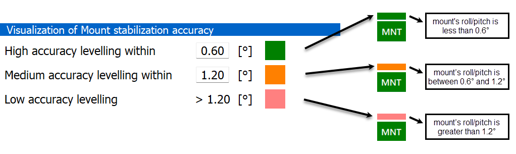
3.1.3. Status of MNT - SOMAG Mount#
Upper box: Value of mount levelling
The levelling is displayed in three classes:
green: high accuracy levelling
orange: medium accuracy levelling
coral: beyond medium accuracy levelling
The limits for high and medium accuracy classification can be defined in the tolerances section of the main menu:
Lower box: MNT status

|
No mount is available. |

|
The mount has an error. |

|
The mount is in MAN mode. |

|
The mount is in STAB mode. |
3.1.4. Status of SCN - Riegl Scanner(s)#

|
No scanner is available. |

|
The scanner is connected and running. It is in not initialized mode. |

|
The scanner is available. It is either not yet connected to SensorHandler/Navigator or it has an error. |

|
Lower box: The scanner is in initialized or in working mode. |

|
Lower box: The scanner is in logging mode. |

|
Lower box: The scanner is in logging mode. Hint Possible causes:
|
3.2. Display control#
3.2.1. Operator display#
Hint
Use Auto zoom settings for global display control.
Important
Almost all view modifications listed below affect only the operator display! The pilot display remains unchanged.
Zoom in |
|
Zoom out |
Click anywhere on the map to manually recenter the display to that location. |
|
Toggle between manual and automatic zoom (applies only to operator display!) |
Display all flight lines of the project (multiline). |
|
Zoom to active flight line (single line). |
|
|
Toggle between centering of the map on airplane |
|
Show/hide the ID of lines |
|
Show/hide the ID of images |
Switch on/off for immediate suspension/resumption of data acquisition for cameras and scanners. |
|
Switch on/off to mark images to be reflown. |
Release a manual trigger |
|
Toggle to enable (green) or disable (red) the digitizing of the airplane’s track to the file track.shp. |
Select a specific flight line from a list of lines. |
|
|
Set current flight line to the previous line (actual line ID -1). |
|
Set current flight line to the next line (actual line ID +1). |
Switch between visualization of only the selected line including its images and of all lines with images. |
|
Filter to show/hide image centers of all successfully taken images. |
Filter to show/hide image centers that have not yet been taken. |
|
Filter to show/hide all triggered images with camera warnings or errors. |
3.2.2. Pilot display#
The few buttons on the pilot display can be selected directly if the pilot has a touch display. Otherwise, the operator can use the extended desktop to control the buttons on the pilot display.

|
Zoom in (disable automatic zooming of the map) |

|
Zoom out (disable automatic zooming of the map) |

|
Return to default zoom |
|
Set current flight line to the previous line (actual line ID -1). |

|
Set current flight line to the next line (actual line ID +1). |